|
1951 Chevy Accessories Installation Manual |
|||
|
14. Assemble Spring, Bearing, Handle and
Handle Screw. Tighten
Screw securely. Rotate Handle
to see that Pinion and gear Racks move freely.
15. Tighten Screw "A" in Housing very securely.
THIS MUST BE DONE
LAST.
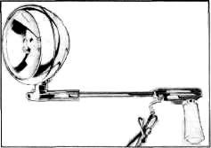
16. Pass the wire from Spot Lamp Handle under
the Bracket (see figure 170).
Leave a loop of wire big enough
to allow 180° rotation of the
lamp Shaft. Screw Bracket firmly into place with oval head sheet metal
screws.
17. Drill one 1/8" diameter hole (see top of
figure 170), Fasten wire along door face with Screw-on Clip at the 1/8" hole and
Clinch-on Clip (see figure
171).
18. Locate tube Clip on door (see figure 171),
and drill two 1/8" holes.
Fasten tube clip to door with
two sheet metal screws.
19. Locate and drill 3/4" hole from Grommet,
(see figure
170).
20. Remove cowl side trim panel and drill 1/4"
hole in hinge reinforcement
(see figure 171) and insert
upper tube clip. With door wide open, pass wire through 3/4" hole,
insert Grommet in place, and fasten
tube in clip.
21. Replace trim panel.
22. Run wire along back of
instrument panel and fasten to main
wire harness with existing clips, as illustrated in figure
172.
23. Remove screw from
indicated terminal on battery side of
accessory junction block and install fuse holder as illustrated in
figure 172.
NOTE: If
car is not equipped with Accessory Junction Block, it may be
purchased under part number 986395
for 1950 and 986442 for
1951. |
 |
||
|
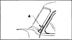
Figure 173
Place template, furnished,
against left-hand corner post and
center punch two screw holes.
Drill two 1/8 inch holes and mount rubber gasket and bracket with two sheet
metal screws furnished, (see
figure 174). |
|||
 |
|||
|
|
|||
|
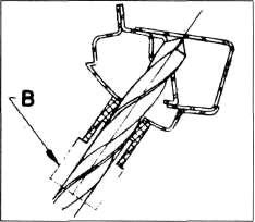
Figure 174 |
|||
|
|
|||
|
Adjustments
Tighten the nut on the Friction
Bracket "J" (see figure 168) to
adjust the tilting of the lamp head to your individual driving needs. This is
the only adjustment necessary
on your Spot Lamp.
Approximate Flat Rate Time 1 hour 986173 SAFETYLIGHT |
 |
||
|
Procedure
for Installation of Safetylight on All Model Trucks.
IMPORTANT:
The truSafetylight is designed to
mount on the left-hand corner post of the truck. |
|||
|
Figure 175 |
|||
|
|
|||
|
72 |
|||
|
|
|||
| « PREVIOUS PAGE | CONTENTS PAGE | NEXT PAGE » |
|
|